DIY Arduino Hydroponics for Automated Grow Box
You’re here to build a DIY automated hydroponics system with your Arduino or ESP32. You’re in the right place. We’ll show you three ways to do this, from a simple offline script to a powerful, app-controlled ‘smart’ system.
The Basic Offline Script (The "DIY" Way)
Looking for a complete, standalone Arduino hydroponics automation script? You're in the right place. This guide provides a full .ino (Arduino) code file that runs 100% offline. It's designed to be a "set it and forget it" system for a small-scale grow.
This script is built to be non-blocking, meaning it uses timers (not delay()) so all your automations (lights, water, sensors) can run at the same time without interfering with each other.
What This Script Automates:
- Light Cycle: Turns a relay ON for a set number of hours (e.g., 18) and OFF for the rest (e.g., 6).
- Watering Cycle: Turns on a water pump for a few seconds (e.g., 30s) every few minutes (e.g., 15 min).
- Root Fan (Optional): Activates a fan relay for a set time right after watering to improve root-zone oxygen.
- Sensor Reading: Reads air temperature/humidity (from a DHT sensor) and water temperature (from a DS18B20 sensor).
- Serial Monitoring: Prints all sensor data and system status to the Serial Monitor so you can see what's happening.
Hardware You'll Need:
- An Arduino (UNO, Nano, or Mega) or ESP32/ESP8266.
- A 4-channel Relay Module.
- A DHT22 or DHT11 sensor (for air temp/humidity).
- A DS18B20 waterproof temperature sensor.
- A 4.7k Ohm resistor (for the DS18B20) or DS18B20 "Plug Adapter" (has built-in 4.7k Ohm resistor)
- Jumper wires and a breadboard.
Wiring Diagrams
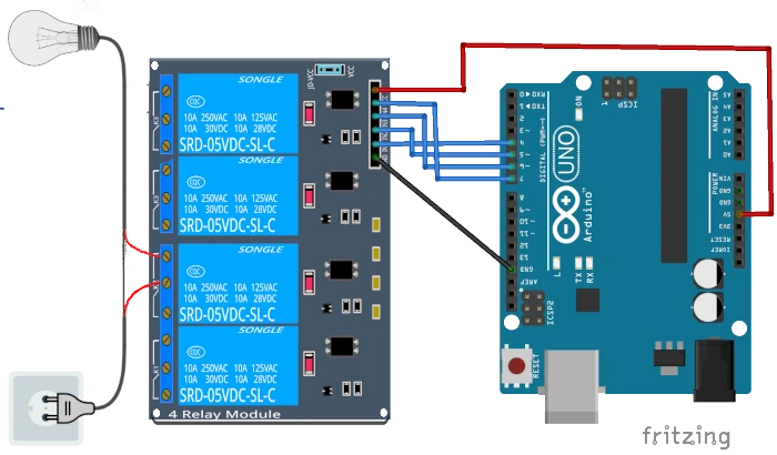
Part 1 — Relays (4-Channel Relay Module)
This section explains how to connect a 4-channel relay board to an Arduino/ESP32 and how appliances are wired for hydroponics automation.
Relay wiring basics:
- VCC → 5V
- GND → GND
- IN1–IN4 → Arduino/ESP32 digital pins
- Use a 5V relay module (with optocoupler) for electrical isolation
Safety for appliances (shown in diagram):
- Mains AC power goes into COM, and your appliance connects to NO (Normally Open)
- Examples included:
- Grow light
- Ventilation fan
- Root-zone fan
- Water pump
This allows your Arduino or GEIA-compatible board to switch each appliance ON/OFF safely without high voltage going through the microcontroller.
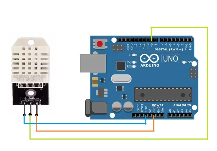
Part 2: DHT22 (Temperature & Humidity Sensor)
Wire the DHT22 to the Arduino as follows:
- VCC → 3.3V or 5V (depending on your module)
- GND → GND
- DATA → any digital input pin
- Use a 10k pull-up resistor between DATA and VCC if your module doesn’t already include one.
This sensor is easy to use but slightly slower and less accurate than SHT31, perfect for basic automation.
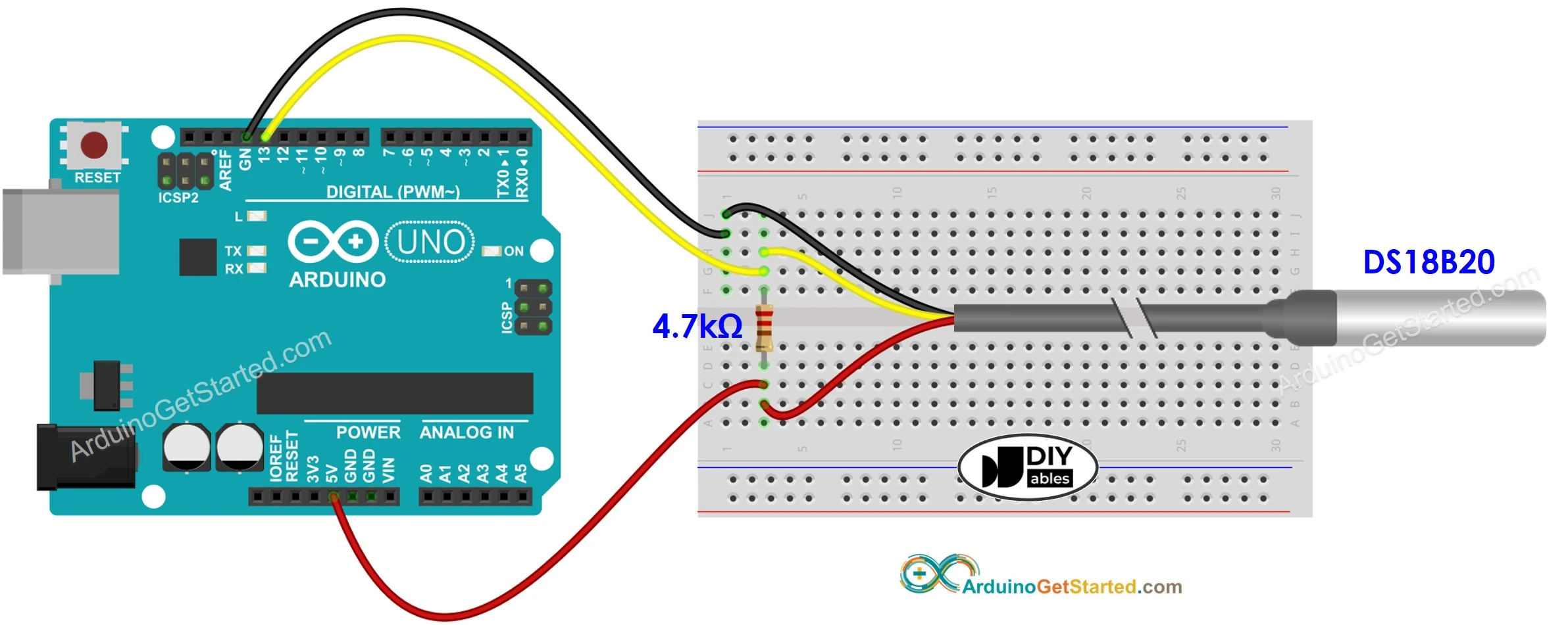
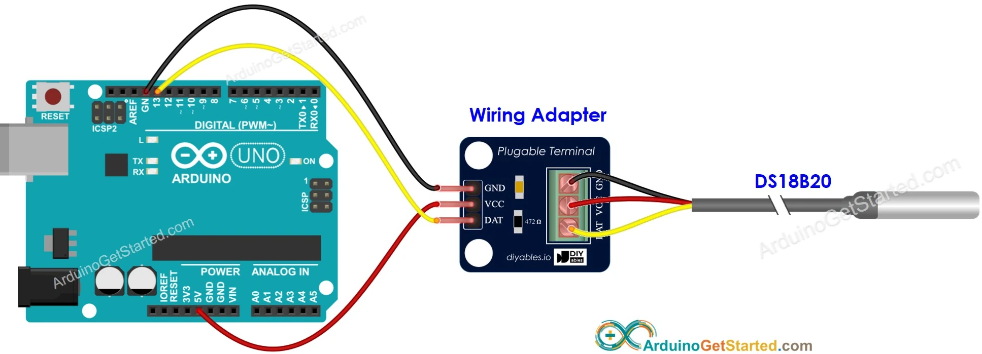
Part 3 - Wiring DS18B20 (Water Temperature Sensor)
The DS18B20 uses the OneWire protocol and works beautifully in hydroponics systems for nutrient-water temperature monitoring.
Connections:
- VCC → 3.3V or 5V
- GND → GND
- DATA → any digital pin
- Add a 4.7k pull-up resistor between DATA and VCC (Unless you use DS18B20 with "Plug Adapter" module board which includes the resistor)
Notes:
- Waterproof DS18B20 probes (the stainless-steel tube type) are recommended for deep-water culture or aeroponics reservoirs.
- Multiple DS18B20 sensors can share the same DATA wire — each sensor has a unique internal address (You will need to adjust code to retrive values of multiple DS sensors, and will need ID for each (by Adding Virtual Sensor in APP).
Part-by-Part Walk-through Guide
Here is how the code is built. You can find the complete, copy-paste script in the next section.
Part 1: Libraries, Pins, and Timers
First, we include the libraries needed for our sensors. We define which pins our relays are connected to and set up all the variables for our timers. This is where you can customize your cycle times.
#include <DHT.h>
#include <OneWire.h>
#include <DallasTemperature.h>

// --- PIN DEFINITIONS ---
// Define which Arduino pin each relay is connected to
#define LIGHT_RELAY_PIN   4
#define PUMP_RELAY_PIN    5
#define FAN_RELAY_PIN     6

// Define sensor pins
#define DHT_PIN           7
#define ONEWIRE_BUS_PIN   8

// --- RELAY STATE (Important!) ---
// Some relay modules are "LOW" active (turn ON when pin is LOW)
// Change these if your relays work backwards
#define RELAY_ON  LOW
#define RELAY_OFF HIGH

// --- AUTOMATION TIMERS (in milliseconds) ---
// Light Cycle (18 hours ON, 6 hours OFF)
const unsigned long LIGHT_CYCLE_DURATION = 18UL * 60 * 60 * 1000; // 18 hours
const unsigned long DARK_CYCLE_DURATION  = 6UL * 60 * 60 * 1000;  // 6 hours

// Watering Cycle (Pump ON for 30s, every 15 min)
const unsigned long PUMP_ON_DURATION = 30000UL;      // 30 seconds
const unsigned long PUMP_CYCLE_INTERVAL = 15UL * 60 * 1000; // 15 minutes

// Fan Cycle (Fan ON for 2 min after pumping)
const unsigned long FAN_ON_DURATION = 120000UL;     // 2 minutes

// Sensor Reading (Read every 5 seconds)
const unsigned long SENSOR_READ_INTERVAL = 5000UL;

// --- SENSOR SETUP ---
#define DHT_TYPE DHT22   // Change to DHT11 if that's what you have
DHT dht(DHT_PIN, DHT_TYPE);
OneWire oneWire(ONEWIRE_BUS_PIN);
DallasTemperature sensors(&oneWire);

// --- GLOBAL TIMER VARIABLES ---
// These are used by the loop to track time
unsigned long lastSensorRead = 0;
unsigned long lastWateringCycleStart = 0;
unsigned long lastPumpOnTime = 0;
unsigned long lastFanOnTime = 0;

// --- STATE MANAGEMENT ---
// This tracks what the watering system is doing
// 0 = IDLE, 1 = PUMPING, 2 = FAN_ONLY
int wateringState = 0;
Part 2: The setup() Function
This runs once when the Arduino boots. It starts the Serial Monitor, sets all our relay pins as outputs (and turns them OFF), and initializes the sensors.
void setup() {
  Serial.begin(115200);
  Serial.println("Arduino Hydroponics Automation - OFFLINE SCRIPT");

  // Set relay pins to output and turn them all off
  pinMode(LIGHT_RELAY_PIN, OUTPUT);
  pinMode(PUMP_RELAY_PIN, OUTPUT);
  pinMode(FAN_RELAY_PIN, OUTPUT);

  digitalWrite(LIGHT_RELAY_PIN, RELAY_OFF);
  digitalWrite(PUMP_RELAY_PIN, RELAY_OFF);
  digitalWrite(FAN_RELAY_PIN, RELAY_OFF);

  // Start sensors
  dht.begin();
  sensors.begin();
}
Part 3: The Automation Functions
These are our "worker" functions. The main loop() will call these to check if any action is needed. Using millis() instead of delay() means none of these functions block the others.
void handleLights() {
  // Get the "time since boot" and find where we are in a 24-hour cycle
  unsigned long timeOfDay = millis() % (LIGHT_CYCLE_DURATION + DARK_CYCLE_DURATION);

  if (timeOfDay < LIGHT_CYCLE_DURATION) {
    // We are in the "Lights ON" part of the cycle
    digitalWrite(LIGHT_RELAY_PIN, RELAY_ON);
  } else {
    // We are in the "Lights OFF" part of the cycle
    digitalWrite(LIGHT_RELAY_PIN, RELAY_OFF);
  }
}

void handleWatering(unsigned long now) {

  // State 0: IDLE (Waiting for next cycle)
  if (wateringState == 0) {
    if (now - lastWateringCycleStart >= PUMP_CYCLE_INTERVAL) {
      // Time to start the pump
      Serial.println("Starting pump...");
      digitalWrite(PUMP_RELAY_PIN, RELAY_ON);

      lastPumpOnTime = now; // Record when the pump turned on
      wateringState = 1;      // Move to "PUMPING" state
    }
  }

  // State 1: PUMPING (Pump is running)
  else if (wateringState == 1) {
    if (now - lastPumpOnTime >= PUMP_ON_DURATION) {
      // Pump has run long enough, turn it off
      digitalWrite(PUMP_RELAY_PIN, RELAY_OFF);

      // Now, turn on the root fan
      Serial.println("Pump OFF. Starting root fan...");
      digitalWrite(FAN_RELAY_PIN, RELAY_ON);

      lastFanOnTime = now; // Record when the fan turned on
      wateringState = 2;   // Move to "FAN_ONLY" state
    }
  }

  // State 2: FAN_ONLY (Fan is running)
  else if (wateringState == 2) {
    if (now - lastFanOnTime >= FAN_ON_DURATION) {
      // Fan has run long enough, turn it off
      Serial.println("Fan OFF. Cycle complete.");
      digitalWrite(FAN_RELAY_PIN, RELAY_OFF);

      wateringState = 0; // Return to "IDLE" state
      lastWateringCycleStart = now; // Reset the main cycle timer
    }
  }
}

void readSensors(unsigned long now) {
  if (now - lastSensorRead >= SENSOR_READ_INTERVAL) {
    lastSensorRead = now; // Reset the sensor timer

    // Read Air Temp & Humidity
    float h = dht.readHumidity();
    float t = dht.readTemperature(); // Celsius

    // Read Water Temp
    sensors.requestTemperatures();
    float waterTempC = sensors.getTempCByIndex(0);

    // Print all data to the Serial Monitor
    Serial.println("--- SENSOR READ ---");
    Serial.print("Air Temp: "); Serial.print(t); Serial.println(" *C");
    Serial.print("Humidity: "); Serial.print(h); Serial.println(" %");
    Serial.print("Water Temp: "); Serial.print(waterTempC); Serial.println(" *C");
    Serial.println("---------------------");
  }
}
Part 4: The Main loop()
The main loop is now incredibly simple. It just gets the current time and passes it to each "worker" function on every single loop.
void loop() {
  // Get the current time once at the start of the loop
  unsigned long currentMillis = millis();

  // Call each automation function.
  // They will decide for themselves if it's time to act.
  handleLights();
  handleWatering(currentMillis);
  readSensors(currentMillis);
}
Complete Offline Arduino Hydroponics Script
Here is the full, copy-paste code for your Arduino.
// LIBRARIES
#include <DHT.h>
#include <OneWire.h>
#include <DallasTemperature.h>


// --- 1. PIN DEFINITIONS ---
#define LIGHT_RELAY_PIN   4
#define PUMP_RELAY_PIN    5
#define FAN_RELAY_PIN     6
#define DHT_PIN           7
#define ONEWIRE_BUS_PIN   8

// --- 2. RELAY STATE ---
// Change to HIGH if your relays are "HIGH Active"
#define RELAY_ON  LOW
#define RELAY_OFF HIGH

// --- 3. AUTOMATION TIMERS (in milliseconds) ---
// Light Cycle (18 hours ON, 6 hours OFF)
const unsigned long LIGHT_CYCLE_DURATION = 18UL * 60 * 60 * 1000; // 18 hours
const unsigned long DARK_CYCLE_DURATION  = 6UL * 60 * 60 * 1000;  // 6 hours

// Watering Cycle (Pump ON for 30s, every 15 min)
const unsigned long PUMP_ON_DURATION = 30000UL;      // 30 seconds
const unsigned long PUMP_CYCLE_INTERVAL = 15UL * 60 * 1000; // 15 minutes

// Fan Cycle (Fan ON for 2 min after pumping)
const unsigned long FAN_ON_DURATION = 120000UL;     // 2 minutes

// Sensor Reading (Read every 5 seconds)
const unsigned long SENSOR_READ_INTERVAL = 5000UL;

// --- 4. SENSOR SETUP ---
#define DHT_TYPE DHT22   // Change to DHT11 if needed
DHT dht(DHT_PIN, DHT_TYPE);
OneWire oneWire(ONEWIRE_BUS_PIN);
DallasTemperature sensors(&oneWire);

// --- 5. GLOBAL TIMER & STATE VARIABLES ---
unsigned long lastSensorRead = 0;
unsigned long lastWateringCycleStart = 0;
unsigned long lastPumpOnTime = 0;
unsigned long lastFanOnTime = 0;
int wateringState = 0; // 0=IDLE, 1=PUMPING, 2=FAN_ONLY

// =======================================================
//   SETUP: Runs once at the beginning
// =======================================================
void setup() {
  Serial.begin(115200);
  Serial.println("Arduino Hydroponics Automation - OFFLINE SCRIPT");

  // Set relay pins to output and turn them all off
  pinMode(LIGHT_RELAY_PIN, OUTPUT);
  pinMode(PUMP_RELAY_PIN, OUTPUT);
  pinMode(FAN_RELAY_PIN, OUTPUT);

  digitalWrite(LIGHT_RELAY_PIN, RELAY_OFF);
  digitalWrite(PUMP_RELAY_PIN, RELAY_OFF);
  digitalWrite(FAN_RELAY_PIN, RELAY_OFF);

  // Start sensors
  dht.begin();
  sensors.begin();
}

// =======================================================
//   LOOP: Runs constantly
// =======================================================
void loop() {
  // Get the current time once at the start of the loop
  unsigned long currentMillis = millis();

  // Call each automation function.
  // They will decide for themselves if it's time to act.
  handleLights();
  handleWatering(currentMillis);
  readSensors(currentMillis);
}

// =======================================================
//   AUTOMATION FUNCTIONS
// =======================================================

/**
 * Handles the 24-hour light cycle.
 * WARNING: This is based on when the Arduino was plugged in.
 * If power is lost, the cycle resets.
 */
void handleLights() {
  unsigned long timeOfDay = millis() % (LIGHT_CYCLE_DURATION + DARK_CYCLE_DURATION);

  if (timeOfDay < LIGHT_CYCLE_DURATION) {
    digitalWrite(LIGHT_RELAY_PIN, RELAY_ON);
  } else {
    digitalWrite(LIGHT_RELAY_PIN, RELAY_OFF);
  }
}

/**
 * Handles the watering state machine.
 * 0=IDLE, 1=PUMPING, 2=FAN_ONLY
 */
void handleWatering(unsigned long now) {

  // State 0: IDLE (Waiting for next cycle)
  if (wateringState == 0) {
    if (now - lastWateringCycleStart >= PUMP_CYCLE_INTERVAL) {
      Serial.println("Starting pump...");
      digitalWrite(PUMP_RELAY_PIN, RELAY_ON);
      lastPumpOnTime = now;
      wateringState = 1;
    }
  }

  // State 1: PUMPING (Pump is running)
  else if (wateringState == 1) {
    if (now - lastPumpOnTime >= PUMP_ON_DURATION) {
      digitalWrite(PUMP_RELAY_PIN, RELAY_OFF);
      Serial.println("Pump OFF. Starting root fan...");
      digitalWrite(FAN_RELAY_PIN, RELAY_ON);
      lastFanOnTime = now;
      wateringState = 2;
    }
  }

  // State 2: FAN_ONLY (Fan is running)
  else if (wateringState == 2) {
    if (now - lastFanOnTime >= FAN_ON_DURATION) {
      Serial.println("Fan OFF. Cycle complete.");
      digitalWrite(FAN_RELAY_PIN, RELAY_OFF);
      wateringState = 0;
      lastWateringCycleStart = now;
    }
  }
}

/**
 * Reads all sensors and prints to Serial Monitor
 */
void readSensors(unsigned long now) {
  if (now - lastSensorRead >= SENSOR_READ_INTERVAL) {
    lastSensorRead = now;

    float h = dht.readHumidity();
    float t = dht.readTemperature();
    sensors.requestTemperatures();
    float waterTempC = sensors.getTempCByIndex(0);

    Serial.println("--- SENSOR READ ---");
    Serial.print("Air Temp: "); Serial.print(t); Serial.println(" *C");
    Serial.print("Humidity: "); Serial.print(h); Serial.println(" %");
    Serial.print("Water Temp: "); Serial.print(waterTempC); Serial.println(" *C");
    Serial.println("---------------------");
  }
}
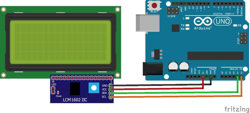
Want to see your sensor data without plugging in a laptop? You can easily add an I2C LCD display.
Code Snippet: You'll need the LiquidCrystal_I2C library. Then, add this to your code:
#include <LiquidCrystal_I2C.h>


// Initialize LCD (address 0x27 is common, 4 rows, 20 cols)
LiquidCrystal_I2C lcd(0x27, 20, 4);

void setup() {
  // ... (inside your existing setup function)
  lcd.init();
  lcd.backlight();
  lcd.setCursor(0, 0);
  lcd.print("GEIA Offline v1.0");
}

// Modify your readSensors() function:
void readSensors(unsigned long now) {
  if (now - lastSensorRead >= SENSOR_READ_INTERVAL) {
    // ... (all the sensor reading code is the same)

    // --- OLD SERIAL CODE ---
    // Serial.println("--- SENSOR READ ---");
    // ...

    // --- NEW LCD CODE ---
    // Row 0: Air Temp / Humidity
    lcd.setCursor(0, 0);
    lcd.print("Air: ");
    lcd.print(t);
    lcd.print("C  ");
    lcd.print(h);
    lcd.print("%   ");

    // Row 1: Water Temp
    lcd.setCursor(0, 1);
    lcd.print("Water Temp: ");
    lcd.print(waterTempC);
    lcd.print("C  ");

    // Row 2: Watering Status
    lcd.setCursor(0, 2);
    lcd.print("Water Status: ");
    if (wateringState == 0) lcd.print("IDLE    ");
    if (wateringState == 1) lcd.print("PUMPING ");
    if (wateringState == 2) lcd.print("FAN ON  ");

    // Row 3: Light Status
    lcd.setCursor(0, 3);
    lcd.print("Lights: ");
    if (digitalRead(LIGHT_RELAY_PIN) == RELAY_ON) lcd.print("ON      ");
    else lcd.print("OFF     ");
  }
}
I2C LCD Display Wiring Diagram
The Problem with This Offline Script
You've now built a 100% offline Arduino hydroponics automation system. It works, but you will quickly discover its frustrating limitations:
- The "Power Fail" Problem: The light cycle is based on
millis(), which is just a timer since the Arduino was plugged in. If your power flickers at 3 AM, your Arduino reboots. It thinks 3:01 AM is the start of its "day," and it will turn your lights on, completely ruining your 18/6 light schedule. - It's "Dumb": The logic is fixed. Want to change the watering from 30s to 35s? You have to plug in your laptop, find the code, change the
PUMP_ON_DURATIONvariable, and re-upload the entire script. - No Data or Alerts: Is your water temperature too high? You'll only know if you're physically there to read the Serial Monitor or LCD. You can't check it from your phone, get alerts, or see historical charts to find out what went wrong.
You've built a timer. To build a truly smart system, you need an upgrade.
Ready for the solution? See how you can fix all these problems for free in Tab 2: The 'Smart' Platform, using the exact same hardware.
Your Hardware, Using our Free Platform
Remember the "Power Fail" problem and the hassle of re-uploading code just to change a timer? This method fixes all of that.
This is the "smart" upgrade to the offline script. You use the exact same hardware, but instead of writing your own code, you flash the free GEIA.AI firmware.
This turns your project into a powerful, app-controlled system.
Why This Method is Better:
- Completely Code-Free: No more C++ or complex logic. You use a simple "no-code" automation builder in our app.
- Easy Setup: You'll be online in minutes using our firmware installer.
- 100% Free: The platform is free for DIYers.
- Solves All Tab 1 Problems:
- 📱 Remote App Control: Check your farm from anywhere.
- 📈 Data Logging & Charts: See your sensor history.
- 🔔 Instant Alerts: Get notified if your pump fails or temp is too high.
- 💾 Cloud Backups: Your schedules are safe, even if the power fails.
Choose Your Hardware
You have two options to get started.
Option A: Use Your Own Board (The Free Way)
You can use the exact same ESP32/ESP8266 or Arduino-compatible board you planned for the offline script. We'll just be flashing it with the GEIA.AI firmware instead of your own.
#la_icon_boxes_697af1054aeef.la-sc-icon-boxes .wrap-icon .box-icon span{line-height:180px;font-size:180px;width:180px;height:180px}#la_icon_boxes_697af1054b28f.la-sc-icon-boxes .wrap-icon .box-icon span{line-height:180px;font-size:180px;width:180px;height:180px}
- Account: Create an account in the GEIA shop and app.
- Supported Board: Arduino-compatible boards (ESP8266 & ESP32*).
- Relay/s: Any relay that works with your board and compatible with the appliance load's.
- Supported Sensors (Optional): Any compatible sensors for monitoring your grow environment.
- Wires & Soldering: Basic wiring and soldering tools may be needed.
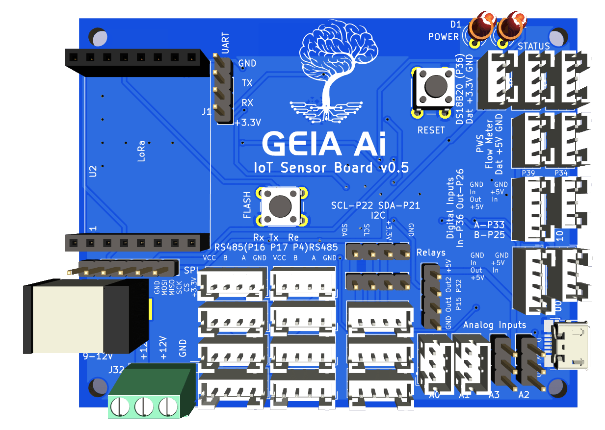
- Master Grow Hub Unit (Optional): For enhanced features and bullet-proof reliability.
- 3D Printer (Optional): For printing custom components and enclosures.
*ESP32 support is currently limited and is exclusively available on the Geia IoT Precision Farming Board.
Download & Install Firmware
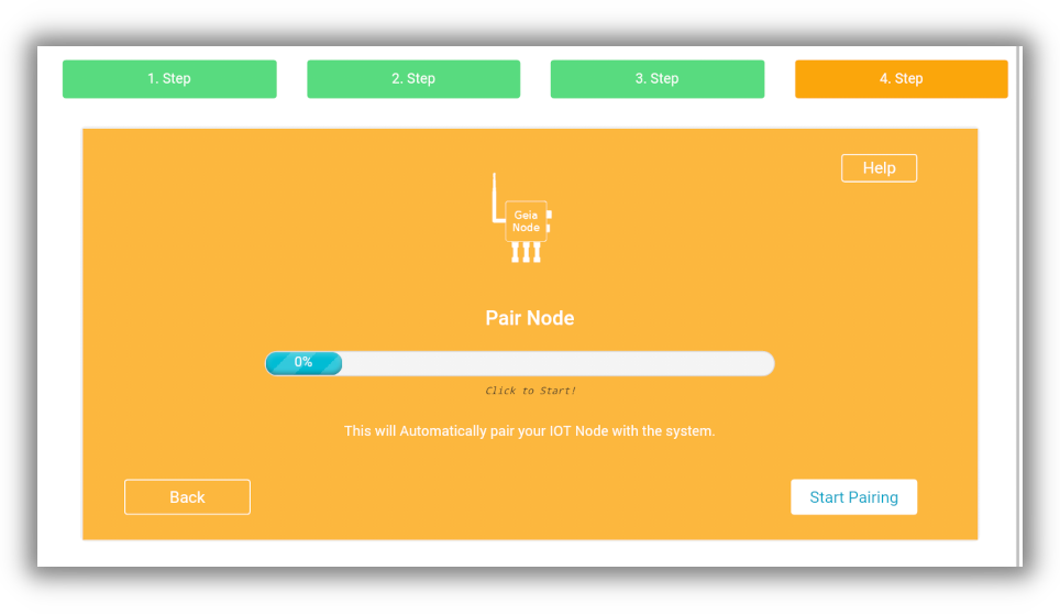
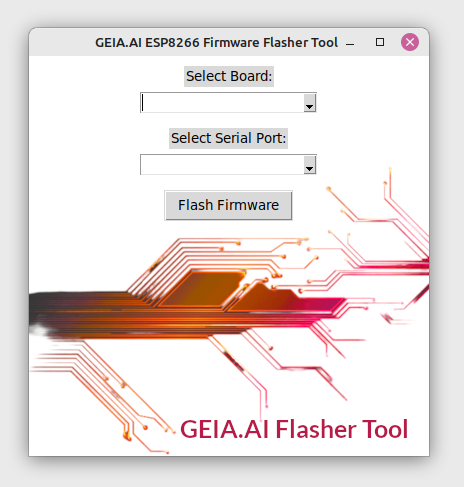
Download the firmware flashing tool, select compatible ESP8266 or ESP32 board and click flash to flash firmware to the board. Once completed the board LED should be flashing.
Download for Windows
<strong>Supported Versions</strong>: Windows 10 and 11 (64-bit)
<strong>Supported Distributions</strong>: Ubuntu, Debian, Mint, Fedora, Arch
Download for macOS
<strong>Supported Versions</strong>: macOS 11 (Big Sur) and later
<strong>Requirements</strong>: Python 3.7+, Git, pip
1. Connect Relays to Your Board
Attach relays to the ESP board’s GPIO pins and connect 5v and GND wires. check your arduino board pinout diagram for a suitable pins (All Digital).
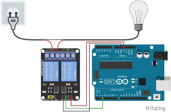
Note: Each relay offers both NC (Normally Closed) and NO (Normally Open) options. While GEIA supports both configurations, most appliances typically use the NC setting unless otherwise specified.
Important Notice: Standard 5V relays commonly used with Arduino can support a maximum of 230V at 10A (up to 2500W), 110V at 10A (up to 1100W), and 28V DC at 10A (up to 280W). However, when operated close to these limits, relays may occasionally malfunction or become stuck. To ensure safe operation, please verify that the connected appliance remains below these thresholds.
1. Attach Sensor/s to the Board
Connect each sensor to compatible GPIO pin on the ESP board (Digital/I2C/Analog). Sensors can be set up to track various data points and logged in real-time through the app.
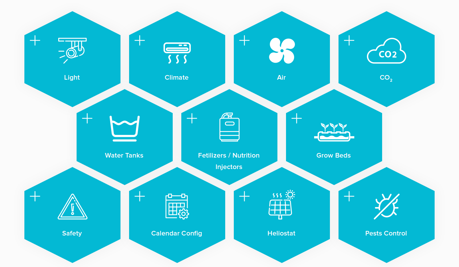
The GEIA app includes customizable automation routines to optimize your grow box, so you can automatically control light, temperature, water levels, and more.
Possible Automations:
-
- Lighting: Automate grow lights, backup lights, monitor light intensity, and save energy by adjusting based on ambient light.
- Climate Control: Track and control humidity and temperature for ideal growth conditions.
- Air Ventilation: Adjust air ventilation, cool tubes, and airflow based on CO2 levels or temperature.
- Water Management: Monitor water tank levels, refill or drain automatically, and track/control pH, EC, TDS, ORP and dissolved oxygen (DO).
- Nutrition Dosing: Use DIY DoseMate pumps or relay-activated pumps to add nutrients, especially useful for larger water tanks (500L+).
- Root Zone Control: Monitor and control root temperature and humidity and ventilate roots in aeroponics setups.
Your Costume Code, Using our Free Platform
For advanced developers or hired engineers, this method offers the best of both worlds: write your own custom hydroponics automation logic on Arduino/ESP32 while leveraging the GEIA.AI ecosystem for dashboards, historical logging, and remote control.
This hybrid approach is perfect if you need specific, complex logic (e.g., custom nutrient mixing) but don't want to build a mobile app or database from scratch. It supports both Offline Control (via Master Hub) and Cloud Logging.
Why Developers Choose This Path:
- Total Logic Control: You own the loop. Write complex C++ automation without restrictions.
- Instant UI: No need to build a frontend. Your sensors automatically populate charts and dashboards in the GEIA app.
- Automatic integration with dashboards for logs, charts, and alerts.
- Reliability: Use GEIA’s infrastructure to handle user authentication, data storage, and alerts.
- Offline Capable: Works locally with the Master Grow Hub, so your farm keeps running even if the internet cuts out.
- Scalable: Easily replicate your code across multiple nodes using generic ESP32s.
- Account: Create an account in the GEIA shop and app.
- Supported Board: Arduino-compatible boards (ESP8266 & ESP32*).
- Relay/s: Any relay that works with your board and compatible with the appliance load's.
- Supported Sensors (Optional): Any compatible sensors for monitoring your grow environment.
- Wires & Soldering: Basic wiring and soldering tools may be needed.
- Master Grow Hub Unit (Optional): For enhanced features and bullet-proof reliability.
- 3D Printer (Optional): For printing custom components and enclosures.
*ESP32 support is currently limited and is exclusively available on the Geia IoT Precision Farming Board.
Get Your Credentials: Sign up at GEIA.AI
During signup, Make sure EcoSystem Partner is selected, then Select Developer and Interest step, select Generate API Access, You will then receive API Authentication details:
- API Key (JWT Token)
- API Refresh Token
- Assigned server cluster address
- MQTT Authentication Token
- Location ID
Please note that the credentials will be sufficient for testing and developing.
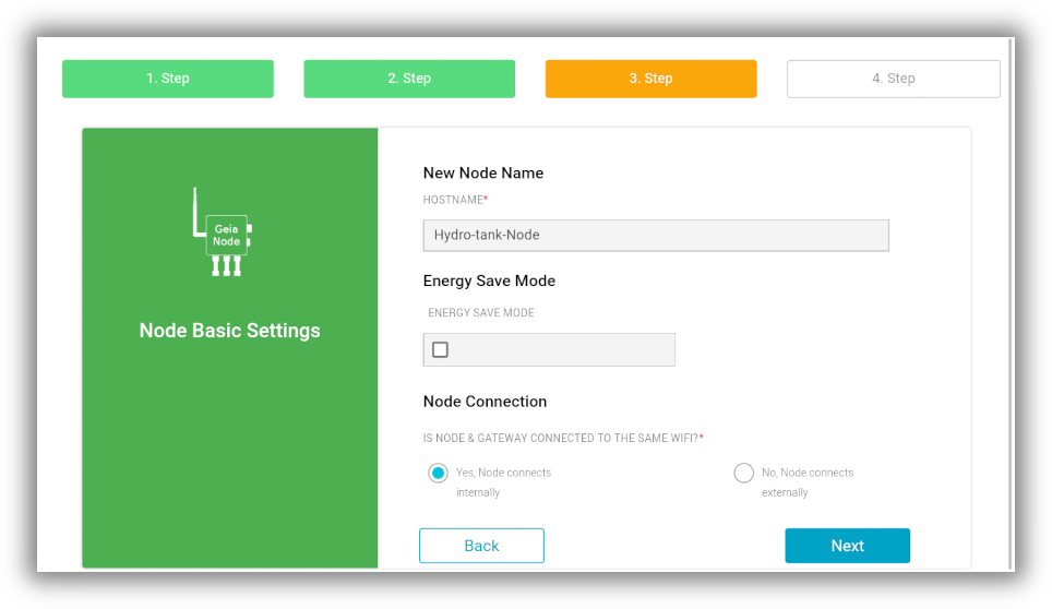
When creating a new node in app, you will receive credentials for the specific node, its recommended to use them in your Arduino code when going live - for test purpose initial credentials will be sufficient.
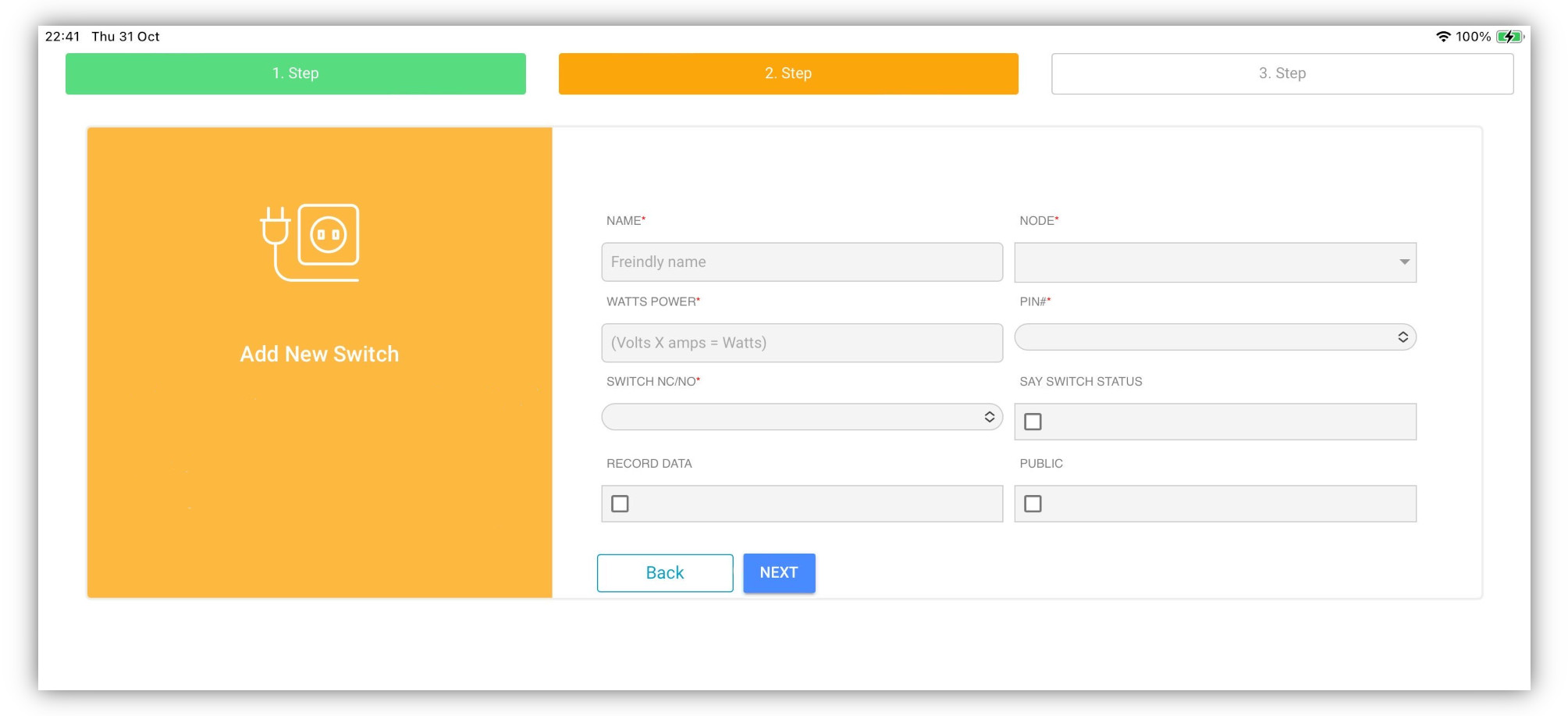
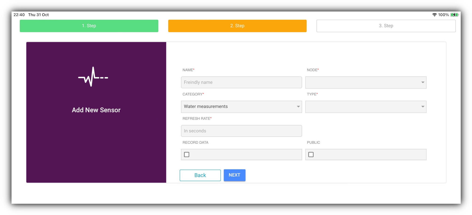
Create Virtual Relays/Sensors: Add sensors or relays to that node to get their specific Component IDs. You will use these IDs in your MQTT topics and RestAPI.
Select Virtual Sensor Option, and if sensor is not in the list, select unknown sensor.
Use this code to: Connect a physical sensor (like DHT22/SHT31) and a wired relay to the GEIA platform (Offline or Cloud) - using MQTT messaging protocol.
How it works: It publishes live sensor data to the dashboard and listens for control commands from the app to switch the wired relay.
This also allows you to use sensors not supported yet by GEIA but still use it in automations or log its data in chart.
It includes "Non-blocking" timers so the connection stays stable, and handles the GEIA Relay "Force Logic" Switch (which allows you to manually override automation from the app).
#include <WiFi.h>
#include <PubSubClient.h>

// --- 1. CONFIGURATION ---
const char* ssid = "YOUR_WIFI_SSID";
const char* password = "YOUR_WIFI_PASSWORD";

// Server Settings
// For Cloud: Use "mqtt.geia.ai"
// For Local MasterHub: Use the IP address of your Hub (e.g., "192.168.1.50")
const char* mqttServer = "mqtt.geia.ai";
const char* mqttUser = "YOUR_API_TOKEN"; 	// Token from App
const char* mqttPass = "YOUR_API_PASSWORD";   	// Password from App

// --- 2. TOPIC & ID SETUP ---
// IMPORTANT:
// If using Cloud: Set location_prefix to "YOUR_LOCATION_ID/" (e.g., "77/")
// If using Local MasterHub: Set location_prefix to "" (Empty String)
String location_prefix = "e/77"; // Use "" for Master Hub
const char* sensor_id = "12345";  //Get this ID from GEIA App (Sensor Settings)
const char* relay_id = "67890";   // Get this ID from GEIA App (Relay Settings)
const int relayPin = 2; // The GPIO pin your relay is connected to	on	Arduinoi/ESP

WiFiClient espClient;
PubSubClient client(espClient);

// Timers (Non-blocking delays)
// We use millis() instead of delay() so the MQTT connection doesn't drop
unsigned long lastMsg = 0;
const long interval = 30000; // Send sensor data every	30 Seconds interval
float lastTemp = 0.0;
float lastHum = 0.0;

// Logic State variables
bool automationOff = false;
int forceStatus = -1;

// --- SENSOR MOCKUP ---
// Replace these functions with your actual library calls (e.g., dht.readTemperature())
float readTemperature() { return 22.5; }
float readHumidity() { return 55.1; }

void setup() {
  pinMode(relayPin, OUTPUT);
  digitalWrite(relayPin, LOW);	// Default to OFF
  Serial.begin(115200);

  setup_wifi();
  client.setServer(mqttServer, 1883);
  client.setCallback(mqttCallback);	// Register function to handle incoming msgs
}

void setup_wifi() {
  WiFi.begin(ssid, password);
  while (WiFi.status() != WL_CONNECTED) { delay(500); Serial.print("."); }
  Serial.println("\nWiFi connected");
}

void loop() {
  // Ensure we stay connected to MQTT
  if (!client.connected()) reconnectMQTT();
  client.loop();

   // --- NON-BLOCKING TIMER ---
  // This allows the loop to keep running fast to listen for commands
  unsigned long now = millis();
  if (now - lastMsg > interval) {
    lastMsg = now;
    checkAndPublish();
  }
}

void checkAndPublish() {
  float temp = readTemperature();
  float hum = readHumidity();

  // CHANGE DETECTION: Only publish if values changed by > 0.1
  // This saves data and reduces clutter
  if (abs(temp - lastTemp) > 0.1 || abs(hum - lastHum) > 0.1) {

    // Payload Format: Space separated ("Value1 Value2")
    String payload = String(temp, 1) + " " + String(hum, 1);

    // Construct Topic: [Location_Prefix] + /e/s/ + [Sensor_ID]
    String topic = (location_prefix.length() > 0 ? location_prefix + "/" : "") + "e/s/" + sensor_id;

    client.publish(topic.c_str(), payload.c_str(), true);
    Serial.println("New Data Published: " + payload);

    lastTemp = temp;
    lastHum = hum;
  }
}


// --- INCOMING COMMAND HANDLER ---
void mqttCallback(char* topic, byte* payload, unsigned int length) {
  String message;
  for (int i = 0; i < length; i++) message += (char)payload[i];

  // Construct topic strings to compare against
  String prefix = (location_prefix.length() > 0 ? location_prefix + "/" : "");
  String switchTopic = prefix + "e/r/" + relay_id + "/switch";
  String forceTopic  = prefix + "e/r/force/" + relay_id;

   // 1. HANDLE FORCE LOGIC (Manual Override)
  // This allows the User in the App to say "Force ON" or "Force OFF"even	if	automation	trying	to	change	the	state
  if (String(topic) == forceTopic) {
    if(message == "0" || message == "0 0") {
      automationOff = false;
    } else if(message == "1 0") {
      automationOff = true;
      digitalWrite(relayPin, LOW);
    } else if(message == "1 1") {
      automationOff = true;
      digitalWrite(relayPin, HIGH);
    }
  }

   // 2. HANDLE NORMAL SWITCH (Automation Commands)
  // Only execute if automation is NOT overridden manually	(Force	Switch	Off)
  if (String(topic) == switchTopic && !automationOff) {
      if (message == "1") digitalWrite(relayPin, HIGH);
      else if (message == "0") digitalWrite(relayPin, LOW);
  }
  //Publish	the	state	of	relay	to	rstate	topic	to	confirm


}

void reconnectMQTT() {
  while (!client.connected()) {
    String clientId = "GEIA-Node-" + String(random(0xffff), HEX);
    if (client.connect(clientId.c_str(), mqttUser, mqttPass)) {
      String prefix = (location_prefix.length() > 0 ? location_prefix + "/" : "");
      client.subscribe((prefix + "e/r/" + relay_id + "/switch").c_str());
      client.subscribe((prefix + "e/r/force/" + relay_id).c_str());
    } else { delay(5000); }
  }
}
How Force Logic Works:
- Force Message →
`0`or`0 0`→ No automation override → Normal`/switch`commands work; relay switches as usual. - Force Message →
`1 0`→ Automation OFF, forced OFF →`/switch`ignored; relay forced OFF - Force Message →
`1 1`→ Automation OFF, forced ON →`/switch`ignored; relay forced ON
Key Points:
- If automation is OFF (1 first digit), the relay ignores
/switch. - The second digit defines forced state only when automation OFF.
- When
0 0, Commands sent to"/switch"works normally and force is removed.
Notes:
- Wired relay controlled by incoming MQTT commands - Controlled by Automation or User inputs in APP.
- If you have MasterGrow Hub, you can use the Offline method by omitting
location_idfrom the topics (delete "String(location_id) +") For Online-Cloud, use the Location ID in topic (by defininglocation_idvariable) - Supports offline/online operation, any ESP32/ESP8266.
For more information:
- Explore the GEIA MQTT API Documentation for details on connecting and interacting via MQTT.
Use this code to: Log sensor and relay data over HTTPS, for historical data and charts.
How it works: Ideal for battery-powered devices (like ESP-NOW gateways) that wake up, send data, and sleep. It handles JWT Token Authentication automatically, if your token expires (Error 401), the code grabs a new one using your refresh token and retries the upload.
Part 1: Setup & Calculation Logic
This part goes in your main loop. It detects when a relay switches and calculates the data.
#include <WiFi.h>
#include <HTTPClient.h>
#include <ArduinoJson.h>

const char* ssid = "YOUR_WIFI";
const char* password = "YOUR_WIFI_PASS";

// State Tracking for Consumption Calculation
unsigned long onTimestamp = 0; // Stores when it turned ON (Epoch or millis)
bool isRelayOn = false;
float deviceWattage = 50.0; // Example: 50 Watt Grow Light

// (Include Part 2 Functions here)

void setup() {
  Serial.begin(115200);
  WiFi.begin(ssid, password);
  while (WiFi.status() != WL_CONNECTED) delay(500);
}

void loop() {
  // EXAMPLE LOGIC: Detecting a switch change
  // In your real code, you call this when you switch your relay

  bool commandToTurnOn = true; // Replace with your actual switch logic

  if (commandToTurnOn && !isRelayOn) {
    // TURN ON EVENT
    isRelayOn = true;
    onTimestamp = millis(); // Or use time(NULL) if you have NTP synced
    Serial.println("Relay Turned ON. Timer Started.");
  }
  else if (!commandToTurnOn && isRelayOn) {
    // TURN OFF EVENT
    isRelayOn = false;
    unsigned long offTimestamp = millis();

    // 1. Calculate Duration (in seconds)
    float durationSeconds = (offTimestamp - onTimestamp) / 1000.0;

    // 2. Calculate Watts Used (Watt-hours or total consumption based on duration)
    // Formula: (Watts * Seconds) / 3600 = Watt-hours
    float wattsUsed = (deviceWattage * durationSeconds) / 3600.0;

    // 3. Send to GEIA API
    logRelayData("RELAY_ID_123", onTimestamp, offTimestamp, wattsUsed);
  }

  delay(1000);
}
Part 2: The API Functions
Copy this below your loop. This handles the connection and token refresh.
// --- GEIA API CONFIG ---
// Check API Docs: This URL may differ based on your cluster
String apiBase = "https://api.geia.ai";

// Initial Credentials (Get these from your App/Profile)
String jwtToken = "YOUR_INITIAL_JWT";
String refreshToken = "YOUR_REFRESH_TOKEN";

// Helper to refresh token if expired
bool refreshJWT();

// Function to log Sensor Data
void logSensorData(String sensor_id, float v1, float v2) {
  HTTPClient http;
  http.begin(apiBase + "/data/add/sensor");
  http.addHeader("Content-Type", "application/json");
  http.addHeader("Authorization", "Bearer " + jwtToken);

  // Create JSON Doc	using ArduinoJson
  // StaticJsonDocument<200> is sufficient for simple data
  StaticJsonDocument<200> doc;
  doc["sensor_id"] = sensor_id;
  doc["value_1"] = v1;
  doc["value_2"] = v2;
  // Note: We omit "sample_timestamp" to let the Server assign the time.
  // If you have an RTC, you can add it here in ISO 8601 format.

  String payload;
  serializeJson(doc, payload);

  // Send Request
  int code = http.POST(payload);

  // --- RETRY LOGIC ---
  // If the server says "401 Unauthorized", our token expired.
  if(code == 401) {
    Serial.println("Token expired. Refreshing...");
    http.end(); // Close old connection

    if(refreshJWT()) {
      // Retry sending data with new token
      HTTPClient httpRetry;
      httpRetry.begin(apiBase + "/data/add/sensor");
      httpRetry.addHeader("Content-Type", "application/json");
      httpRetry.addHeader("Authorization", "Bearer " + jwtToken);
      httpRetry.POST(payload);
      httpRetry.end();
      Serial.println("Data sent after refresh.");
    }
  } else {
    Serial.print("Data Sent. Code: ");
    Serial.println(code);
    http.end();
  }
}


// Function to log Relay Data
void logRelayData(String relay_id, unsigned long on_ts, unsigned long off_ts, float watts) {
  if(WiFi.status() != WL_CONNECTED) return;

  HTTPClient http;
  http.begin(apiBase + "/data/add/relay");
  http.addHeader("Content-Type", "application/json");
  http.addHeader("Authorization", "Bearer " + jwtToken);

  // Build JSON Payload
  StaticJsonDocument<200> doc;
  doc["relay_id"] = relay_id;
  doc["on_timestamp"] = on_ts;   // Start time
  doc["off_timestamp"] = off_ts; // End time
  doc["watts_used"] = watts;     // Calculated consumption

  String payload;
  serializeJson(doc, payload);

  // Send Request
  int code = http.POST(payload);

  // Retry Logic for Expired Token
  if(code == 401) {
    http.end();
    if(refreshJWT()) {
      // Re-initialize and retry
      HTTPClient httpRetry;
      httpRetry.begin(apiBase + "/data/add/relay");
      httpRetry.addHeader("Content-Type", "application/json");
      httpRetry.addHeader("Authorization", "Bearer " + jwtToken);
      httpRetry.POST(payload);
      httpRetry.end();
    }
  } else {
    http.end();
  }
}


// Function to get a new JWT using the Refresh Token
bool refreshJWT() {
  HTTPClient http;
  http.begin(apiBase + "/auth/refresh");
  http.addHeader("Content-Type", "application/json");

  StaticJsonDocument<200> doc;
  doc["refresh_token"] = refreshToken;

  String payload;
  serializeJson(doc, payload);

  int code = http.POST(payload);
  bool success = false;

  if(code == 200){
    StaticJsonDocument<512> resp;
    deserializeJson(resp, http.getString());
    jwtToken = resp["jwt"].as();
    success = true;
  }
  http.end();
  return success;
}
For more information:
- Explore the GEIA REST API Documentation for information on using REST endpoints and integrating with your applications.
Use this code to: Create a local automation controller that acts as a "brain."
How it works: This ESP32 doesn't necessarily have sensors attached. Instead, it subscribes to data from other nodes (via MQTT) and sends commands to other relays. It acts like a custom script running inside the MasterGrow Hub.
Key Feature: Uses "Hysteresis" logic to prevent equipment from damagingly flipping ON/OFF rapidly.
It includes:
- Function to get remote sensor value (MQTT subscribed)
- Function to get remote relay status (MQTT Topic:
e/r/force/{actuator_id}/rstate) - Function to switch relay (MQTT Topic:
e/r/{actuator_id}/switch) - Basic automation function that:
- Reads the sensor
- Decides whether relay should be ON/OFF
- Ensures relay matches expected state
- Reports mismatch errors
Everything is included in one working Arduino/ESP32 sketch.
#include <WiFi.h>
#include <PubSubClient.h>

// --- SETUP ---
String location_id = "LOC123"+"/";  // Leave blank for offline =""; or replace only "LOC123" for Cloud
String sensor_id   = "S1";
String actuator_id = "R1";

const char* ssid = "YOUR_WIFI";
const char* password = "YOUR_WIFI_PASS";
const char* mqtt_server = "ASSIGNED_MQTT_HOSTNAME";

WiFiClient espClient;
PubSubClient client(espClient);

// Data Globals
float remoteSensorValue = -999;
int remoteRelayState = -1;
unsigned long lastRun = 0;

// Topics
String topic_sensor      = location_id + "e/s/" + sensor_id;
String topic_rstate      = location_id + "e/r/force/" + actuator_id + "/rstate";
String topic_relaySwitch = location_id + "e/r/" + actuator_id + "/switch";

void callback(char* topic, byte* message, unsigned int length) {
  String msg = "";
  for (int i = 0; i < length; i++) msg += (char)message[i];
  String t = String(topic);

  if (t == topic_sensor) remoteSensorValue = msg.toFloat();
  if (t == topic_rstate) remoteRelayState = msg.toInt();
}

void setup() {
  Serial.begin(115200);
  WiFi.begin(ssid, password);
  while (WiFi.status() != WL_CONNECTED) delay(500);

  client.setServer(mqtt_server, 1883);
  client.setCallback(callback);
}

void reconnect() {
  while (!client.connected()) {
    String clientId = "AutoBot-" + String(random(0xffff), HEX);
    if (client.connect(clientId.c_str())) {
      client.subscribe(topic_sensor.c_str());
      client.subscribe(topic_rstate.c_str());
    } else { delay(2000); }
  }
}

void runAutomation() {
  if (remoteSensorValue == -999) return;

  // Automation Logic
  bool shouldBeOn = (remoteSensorValue < 20.0); // Temp < 20, Heater ON

  // Command Execution
  if (shouldBeOn && remoteRelayState == 0) {
    client.publish(topic_relaySwitch.c_str(), "1");
    Serial.println("CMD: ON");
  }
  else if (!shouldBeOn && remoteRelayState == 1) {
    client.publish(topic_relaySwitch.c_str(), "0");
    Serial.println("CMD: OFF");
  }

  // --- ERROR DETECTION ---
  // We check if the command failed.
  // If we want it ON, but the remote state confirms it is still OFF (0)
  if (shouldBeOn && remoteRelayState == 0) {
     Serial.println("⚠ CRITICAL FAILURE: Relay is not responding to ON command!");

     // NOTE: GEIA has an API Route for Errors/Notifications.
     // You can use the HTTP logic from Snippet 2 to send this error
     // to /api/log/error so you get a push notification on your phone.
  }
}

void loop() {
  if (!client.connected()) reconnect();
  client.loop();

  if (millis() - lastRun > 2000) {
    lastRun = millis();
    runAutomation();
  }
}
Choose Your Path to Smarter Growing
Start With Software — It’s 100% Free
If you own a compatible board (like an ESP32 or ESP8266), get instant access to the GEIA.AI platform, mobile app, and free firmware for your Arduino hydroponics system now. Bring your first automations online – no hardware purchase required.
Start With Hardware — Plug & Grow
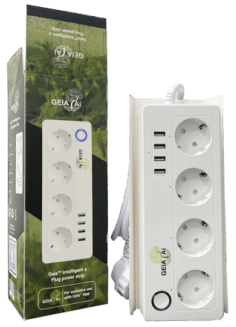
Prefer a faster setup? Choose from pre-flashed control boards, safe plug-and-play relays, and complete DIY kits designed to get your smart system running in minutes.
Arduino Hydroponics FAQ
What is an Automated Grow Box, and how can I set it up for Arduino Hydroponics?
An Automated Grow Box is a self-regulating system for indoor farming that controls light, water, and climate. With Arduino Hydroponics, you can use compatible boards (like ESP8266 or ESP32) to connect sensors and relays to monitor and automate hydroponic systems. Our guide and GEIA app make setup easy for both beginners and experienced growers.
What benefits does an Automated Grow Box offer for Arduino Hydroponics setups?
An Automated Grow Box for Arduino Hydroponics provides precision control over water, light, temperature, and nutrient levels, creating a stable environment with minor fluctuations that reduces plant stress and encourages steady growth. By using the GEIA app, you can easily monitor, adjust, and automate these conditions remotely, lowering the need for constant manual checks. Plus, automated data logging and visualization tools help you identify the “sweet spot” for optimal nutrition absorption, giving insights into when plants use the most nutrients and adjusting accordingly for improved yield and resource efficiency.
Is GEIA Free?
Yes, the GEIA App is free! However, free access has some limits, like data logging every 20 minutes.
Do I need the Master Grow Hub Gateway?
While the Grow Hub isn’t required, it’s highly recommended for safety, precision, and certain extended features. With a Gateway, your automations continue offline, avoiding interruptions due to connectivity issues. In power outages, it resumes operations seamlessly, and it allows multi-zone automation, whereas, without it, automation is limited to one zone.
What sensors are supported?
Check our Supported Sensors List. Note that ESP-based controllers support 3.3-5V sensors with specific connections (I2C, DIGITAL, Analog). Our custom microcontroller board supports a wider sensor range, including industrial sensors, has built-in RS485 support, and accommodates 12V components.
What if my sensor is not supported?
If your sensor isn’t listed as supported yet, you still have several options:
- Request official support: we may ask for a sample sensor to test and validate proper integration.
- Use standard interfaces: GEIA IoT Board supports common protocols such as I²C, RS485, Analog, Digital, and PWM.
- Add your own support: you can extend functionality by writing custom Arduino/ESP code using our guides.
If it speaks standard protocols, GEIA can work with it, via built-in support or simple extensions.
Can I manually log water quality data from test kits or handheld sensors?
Yes! You can log manually-measured data from your paper testing kits or handheld sensors in the app. However, manual data entries can’t be automated, as attached sensors are required for this.
Do I need prior experience with Arduino to set up an Automated Grow Box for hydroponics?
No, prior experience isn’t required! Our Arduino Hydroponics guide simplifies setup and provides step-by-step instructions to help you create your Automated Grow Box, even if you’re a beginner.
Can I add more nodes, sensors, or relays?
Absolutely! You can add and configure multiple nodes, sensors, and relays to suit your system needs.
Do you support the ESP32 Cam?
Yes! ESP32 Cam is supported for beta testers only. Register to become a test user; limited slots are available.
Can I customize my Automated Grow Box setup for both hydroponics and other growing methods?
Yes, absolutely! While Arduino Hydroponics is a popular application, the GEIA platform supports aeroponics, aquaponics, and even soil-based setups. You can easily integrate sensors for various growing conditions and control all aspects from the app, regardless of your growing method.
Additional Features & Use Cases
With your Arduino-compatible board and the GEIA system, you’ll have a fully automated grow box that simplifies your plant management routine.
Main Features:
- Smart irrigation system, supporting indoor/outdoor use
- Works with hydroponics, soil, aeroponics (including high-pressure systems), and aquaponics
- Built-in safety features and fail-safes to protect plants and equipment
- Designed to save energy and water, control molds, and reduce workload
User Cases Include:
- Growhouses, grow tents, or grow beds
- Home gardens or horticulture
- Indoor or outdoor farming setups, including urban farms
- Mushroom grow setups (see guide: GroCycle )
- Aquariums, ponds, and water treatment systems
- Vertical Farming using Hydroponics, Aeroponics and Aquaponics
The GEIA system’s flexibility means it’s adaptable for various applications, from DIY home gardens to professional farming setups.
Extend Your Setup
Need more DIY flexibility or software integrations? Explore our REST API and MQTT options to connect your GEIA system with third-party software or robotics seamlessly. Choose from our available options below to expand and customize your setup:
Modules & Plugins
Discover and share third-party web app modules and plugins that expand the capabilities of GEIA.AI.
Compatible Hardware
Find a list of arduino like micro-controllers that are compatible with GEIA.AI.
3D Printables
Access and share 3D print designs for custom components and enclosures to enhance your GEIA.AI setup.
Robots
Submit your robots or integrate existing ones with GEIA.AI to automate various farming tasks and improve efficiency.
RestAPI Doc
Access detailed documentation on our REST API to seamlessly integrate GEIA.AI with your applications.
MQTT Doc
Learn how to use MQTT to enhance real-time communication and control within your precision farming setup.
Action Hooks
Join our developer community chat to collaborate, share ideas, and get support from fellow developers.
Firmware Tool
Download the firmware tool to upload firmware to supported arduino hardware.


